Three months of procrastinating

Almost three months since the last post here, and really very little progress. Why?

Partly time restrictions, only really able to do much within lunch breaks or maybe 15-30 minutes after hours.

Partly starting to get involved in planning for a total office refit, and desk clearing meaning everything been taped up with masking tape and is currently “stored away”.

Partly needing time to practise a range of new songs for possible gigging.

Partly trying to delay having to do anything with the surface mount component it looks like I’m forced to use in powering the LCD display.

Partly as the fun “idea” stage is behind me and the actual development stage is next, and not only that working out how to turn this from some semi-isolated breadboard test rig to something practical. Stripboard? Custom PCB?

I don’t know if this will change or spur on the project but I have just bought a pre-built display module from SainSmart through Amazon. Just connect to Arduino, write a bunch of code based on examples available on SainSmart’s web site, test. Interestingly this has a touch screen and SD card slot (which actually was how I found out about it).

B.

3rd last “major” purchase…

There was math… and a spreadsheet… and my first use of the LN() function…

Then there was an order of resistors… and capacitors… and inverting Schmitt triggers… and diodes… and more resistors…

Next I’m thinking about the graphical UI, and the buttons… And I almost don’t have a clue…

I’ve sort got a vague vision… in “gig mode” little more than the selected set list and song name, or if you’re scrolling through highlighting either the set or song you will be switching to… In “edit mode” the current parameter will have the prior and next parameter above/below, and the value underneath… Maybe some “soft keys” under the display rather than hardcoding buttons… I “only” have 20 buttons (min order) and I quickly got to 15 before I thought “WOAH!”

Way back in my past I did have experience designing a 2-operator FM synth editor on a 256 by 176 display (256 by 192 pixels with 16 pixel rows “reserved”). Never as small as 160 by 104… that’s equivalent to 20 by 13 characters using 8×8 pixel characters…

Got a feeling I need to re-acquaint myself with the BDF format (may be “source level” altering some stuff), and look at the u8glib project which I’m planning on using for the “hard stuff” for driving the display.

B.

D’oh! About those buttons…

I was going to save doing this next post as “here are the electronics to glue everything together” post… but…

After the last post I placed yet another order for a bunch of resistors, and some “headers” that I’m thinking about using to plug stuff into the Arduino, and for that matter another breadboard seeing as the postage was more than the components, and thought to myself, right that’s it for the electronics. Uhm, yeah that was premature.

There is commonly an issue with pushbuttons, something that might not immediately spring to mind, and that is they “bounce”. You think it’s a clean on/off, especially with a tactile button that resists pressing until suddenly “click” it’s pushed, but it rarely is that simple.

It’s possible to “de-bounce” with software, but it’s also possible to do it with hardware. There are plenty of articles online, but for me, now I’m going down the button route, I think I’ll go for hardware. The method I’ve seen and like the look at works like this.

Take your “current” and run into a resistor (hey look a pull-up resistor), put that into your button and put a capacitor “across” the button, and hooked to ground. Thus the capacitor “charges” when the button is up and discharges when the button is down. To get back to a digital signal (rather than the suddenly distinctly analogue voltage this creates) the “output” of the resistor capacitor series is fed into something called an inverting Schmitt trigger (ooh, at least one more IC). Thus when the capacitor is suitably discharged you suddenly get a “high” meaning “button pressed”.

I have a collection of links to articles, videos, products and the like in Evernote, even “mistakes” and things I’ve decided against, and I think I need to tidy it up and reformat before I miss anything else. At least at this early test/development stage.

B.

I need a what for that?

I was looking through schematics and board layout for a project to integrate a DOGXL160 onto an Arduino shield, and the DOGXL160 tech sheet, and found the power goes through a 100nF (nano-farad) 16V capacitor.

Seems the “best match” I could find for this “teeny” spec component is a “surface mount technology” part. The idea of getting into SMT scares me, but from pictures I could probably take some of that solid core wire I’ve purchased and solder some small lengths on turning it into a very small “through hole” component.

The power circuitry for the screen also needs some 2uF (micro-farad) 16V capacitors according to the spec sheet. The “shield” project specifies 2.2uF, so need some of those too.

Finally on a “logic” level we need to buffer/convert the Arduino 5V outputs down to 3.3V. We have four signals and we’ll follow the “shield” project by using four of the six lines of a “4050” level shifter.

I’ve decided against adding a touch screen to the project, as the connector I’d need is surface mount (see earlier for my thoughts on this). Net result is I need buttons. The tactile buttons I’m looking at right now come in packs of 20. That should do…

All these things are “on order” now, but it dawns on me I must now be close to having all the “electronics” sourced. Need some more stuff for the MIDI side, and look at what I want to do beyond the breadboard testing stage. I think I need another breadboard too now I know I’ll be having probably a fair few buttons to worry about.

I really should start thinking about the code and UI.

B.

Wear levelling your data area?

In an effort to put off having to look too carefully at anything involving amps, volts and ohms (and putting off any decision about user input) I looked at the Arduino specs about memory and looked to ideas about storing the program/bank change and potentially SYSEX.

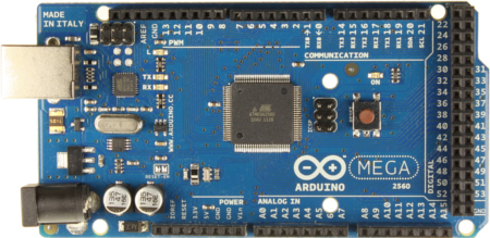
The Mega 2560 has 256K flash for your program code (minus the “bootloader” code) and 8K SRAM for things like variables. Finally there is 4K of EEPROM which can be read from AND written to easily by your program code. This EEPROM is the perfect place for stored but changeable data. It is also rated at 100,000 write cycles.

This sounds like a lot, but in the interest of thinking about how to reduce the wear and tear, and to think of a format for storing the data, I looked at this.

Using some VERY rough calculations, based on a certain number of songs in a “set list”, a certain number of characters in a name, a certain number of program changes and SYSEX messages I came up with a guesstimate (assuming my maths was right) of maybe 320 to 330 bytes for a “set list”, on the basis that a pub/event band might typically have two “sets” for an evening. That comes to around 12 sets able to be stored within 4K.

My idea for a data format assumes the very first “write” to the EEPROM writes zeros to every byte. Then when writing a set list (lets say at the start of memory) it skips over the first byte. If you want to “delete” a set list then the idea is to write some non-zero value into that byte, but leaving everything “intact” such that it can be “skipped over”.

Performance would rely on there only being 4K ever to scan through, and in general this idea will work until you’ve written through the whole memory (minus some remnant at the end), but what then?

Well this is where the plan still needs to be… finessed… Maybe “defrag” if there isn’t enough space at “the end”, shuffling all non-deleted data to the start? Maybe having the deleted flag byte be a sort of age counter thus allowing the use of the use of “gaps” left by deleted data? Then you’d have to be careful where the counter wraps, and if something is “smaller” then you need a means of marking out where the “next” block of data is rather than being directly following.

Of course there is the thought maybe fixing a hard limit on the size of each set list data… say 512 bytes… and carving the 4K space up in those chunks, keeping a “deleted” flag…

This is complete and total overkill really as an even spread might mean between say 800,000 and 1,200,000 set list “saves” to memory?

B.

User Interface, Idea Three, Final (ish)

Some form of sanity prevailed and I decided that if I wanted to go with a graphical display then I should, at least for my first Arduino project, go with something with an already existing library.

I noted two libraries, one seemingly mainly supporting a KS0108 controller, and another, called u8glib supporting that and a few more types besides, though not being hugely conversant with these things maybe they’re “compatible”.

So I went to the RS site, and filtered the displays by all the controllers that appeared on the compatible listing, and after consideration settled on this 160×104 display, and an amber backlight.

I also decided to get some solid core “hook up wire”. This seemed expensive at RS, mainly because it looked like it was in HUGE lengths. So I looked at my usual “fallback” supplier, Amazon.co.uk, and found there were cheap supplies of solid 22 AWG wire. I did have the problem of which colour or colours to choose. In the end I didn’t choose and bought them all as they were relatively cheap.

There is one wrinkle, after placing the order for the LCD display and backlight I was further reading the tech sheet, and noticed there was a touch screen optional extra. At the time of writing I’ve not ordered one, as I’m trying to decide whether to go down that route, or using a range of buttons.

Almost there with the “major” components.

B.

Let’s get some essentials in…

Switching attention away from display and ideas of controls we can get some progress in acquiring parts.

First off, an unescapable requirement is MIDI output sockets. MIDI uses 5-pin 180ยบ DIN sockets, like these.

Secondly, during initial development at least I figured to use a breadboard.

Along with a breadboard I would need to “wire it up”, and for breadboard purposes a nice little jumper wire kit would be very handy.

These “essentials” were all purchased, joining the Arduino in the starts of a pile of parts and components on my desk… at work…

B.

User Interface, Idea Two

I can’t remember quite which order these things happened now, but I discovered there were third party libraries for graphical LCD displays, and interestingly when selecting colour LCDs there was a “touch screen” filter on the RS site.

Suddenly this display became my favourite.

There was the complication that none of the libraries I found claimed any support of this or any of the other similar screens, but I figured worst case surely I could, eventually, work out how to make my own library, maybe looking at specs to a supported screen and seeing what the code was for that – open source models are wonderful sometimes.

I decided not to make any firm decisions for the time being, and started looking at how I was going to start developing my project.

B.

User Interface, Idea One

On reading through the Arduino site, I noticed there was a library called LiquidCrystal to easily control LCD text screens. There were even examples.

So I looked on RS Components site, and as I recall I quite liked this one.

I thought I’d get that, put some buttons around it for control (maybe using left & right sides of the bottom two lines to show the current button operations) and job be done.

When I was looking at buttons and trying to work out sizes I realised how small the display was, and so looked more at character size rather than a 4-line display, and thought about this one instead.

I thought I might end up having more “hard coded” buttons though rather than have part of the display be instructional.

Then came another idea when I was browsing the RS Components site and finding out about some 3rd party libraries for Arduino…

B.

Arduino? OK, but which one?

I have, to date, performed with three different setups:

  1. Roland FP-4F and Roland JUNO-Gi
  2. Roland FP-4F, Roland JUNO-Gi and Nord Electro 3
  3. Roland JUNO-Gi and Nord Electro 3

The FP-4F is a digital piano, and effectively the MIDI In socket let’s you use it as a sound module. Nothing seeming can change the front-panel selection except the buttons.

The JUNO-Gi is very nice, as you have 256 user “patches” which you can name, and the names are shown on the nice large display. With some clever counting of UI elements and the brightness/contrast cranked up, I’ve determined this is a 240 by 64 pixel monochrome screen with the patch named displayed with a font with a 17 pixel high ‘A’ (using the measurement system used in describing the fonts in the u8lib project). You can spin the data wheel round until you find your patch by name or use the numeric entry to directly jump to the patch concerned, or even have “favourites”. This responds nicely to MIDI bank/program changes.

The Nord Electro 3 has 128 patches, all user writeable, but only 3 7-segment displays for reference. The patches are numbered from 1 to 64 which you access with up/down buttons, and with ‘A’ and ‘b’ buttons to double up. This responds nicely to MIDI program changes (no bank selection required).

When I once used an iPad and MIDI interface to manage switching the sounds for each song, I had the JUNO-Gi responding to the changing the front-panel sound on channel 1, and the Electro 3 responding on channel 3, which was handy because the software (Yamaha Set List Organizer) seemingly outputs on every MIDI port it knows.

Ideally I’d like to have something that could maybe send to only a specific device. This would mean having multiple outputs, and for ease of development the plan is to use Arduino serial ports set at 31,250 baud, so this project requires more than one serial TX pin. That means, our Arduino of choice is…

The Arduino Mega 2560

The Arduino Mega 2560

This has four pairs of serial TX/RX pins, so rather than go with just two outputs as I would use right now, let’s go mad and have a MIDI output hooked to all four TX pins. Unless trumped by some other requirement for those pins.

B.